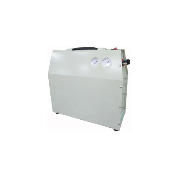
What this configuration is designed to do
Enclosed low-noise family with verified compact dimensions and a catalogue noise-range statement for the silent-box series. The important purchasing distinction is not simply the motor rating or receiver size. A usable selection has to match pressure at the point of use, real air consumption, the length and size of distribution piping, operating pattern, ambient temperature, and how much stored air is available between compressor cycles. The verified model family gives a concrete technical starting point rather than a generic capacity label.
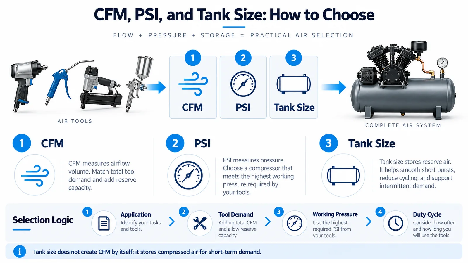
This oil-free receiver compressor should be selected from the duty profile backward. Start with the tools or process, identify simultaneous air demand, then confirm pressure, allowable pressure drop, expected running time and environmental constraints. For a buyer comparing multiple models, the table below is the first filter; final configuration should also include electrical supply, connection size, drainage, ventilation and service access.
Verified configuration and performance data
The published technical values for this page are limited to the documented model family. They are useful for shortlisting, but they should not be stretched into claims about conditions that are not specified. Values such as free-air delivery can change with pressure, while motor loading and thermal behavior depend on operating conditions. When the application includes unusually high ambient temperature, long continuous runs, contaminated intake air or restrictive downstream equipment, include those conditions in the RFQ.
| Voltage / Frequency | 100–415 V / 50–60 Hz |
|---|---|
| Motor power | 320 / 550 / 750 W |
| Air flow | HC280X: 80 L/min @ 0 bar; 30 L/min @ 6 bar; HC1504X/HC1704X: 35 / 50 L/min @ 8 bar |
| Receiver tank | 2 L / 4 L |
| Dimensions | 45 × 18 × 45 cm / 51.5 × 19.9 × 47.2 cm |
| Net weight | 20.7 / 17 / 21 kg |
| Catalogue noise range | 40–53 dB(A) for the silent-box range |
Models covered on this page: HC280X, HC1504X, HC1704X. The practical comparison is to check whether the required pressure and flow fall comfortably inside the selected model’s documented operating range rather than at its limit. If a process has several tools, use the combined demand plus a realistic allowance for leakage and future changes instead of sizing from one nameplate alone.
Product structure and system layout
The core arrangement combines oil-free pump modules and a receiver tank. For receiver models, the tank provides short-term storage and helps absorb differences between compressor delivery and intermittent tool demand. For screw units, the system must be treated as a packaged process machine: intake, compression, cooling, control, piping and the downstream air system interact continuously. A mismatch in any one part can reduce usable pressure or increase operating temperature.
Access around filters, drains, belts or couplings, electrical panels and cooling surfaces should be considered before placement. Installation clearances are not decorative space; they make inspections possible and keep hot discharge air from being recirculated. Service teams should be able to isolate the compressor, depressurize it safely and reach routine-maintenance items without dismantling surrounding equipment.
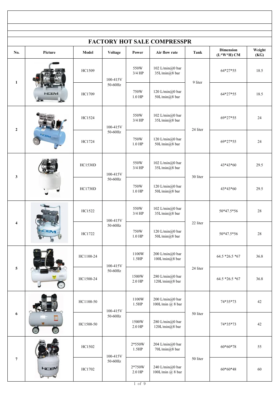
How to match flow, pressure and storage
Pressure and flow answer different questions. Pressure defines the force potential available to a tool or process, while flow determines how much compressed air can be delivered over time. A receiver can cover short peaks, but it cannot replace compressor capacity during sustained demand. When buyers size only from tank volume, the result may recover too slowly; when they size only from motor power, pressure losses in hoses and piping may still leave the tool under-supplied.
For this model family, compare the documented delivery point with the required pressure at the user. Then account for distribution losses, duty cycle and the number of simultaneous consumers. A practical RFQ includes target pressure at the machine, estimated flow, daily operating hours, the longest continuous run and any peak demand. You can compare the related compressor family before finalizing the model.
Applications and duty conditions
The natural fit is intermittent workshop, service, inflation and equipment-support duty. In construction and maintenance work, portability and recovery time can matter more than a large stationary receiver. In indoor workshops, noise, ventilation and electrical compatibility rise in priority. In production processes, the decisive factors shift toward stable pressure, air quality, continuous-duty behavior, cooling and planned maintenance. Medium- and high-pressure systems add another layer: every downstream component must be suitable for the actual operating pressure.

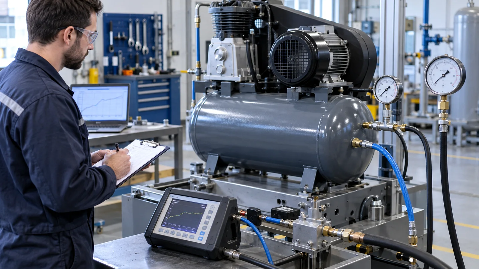

Application scenes illustrate typical working contexts rather than claiming a specific installed customer project. For unusual process air, share the gas/air composition, inlet conditions, pressure requirement, contamination limits and duty profile so the selection can be reviewed against the actual system.
Installation planning before commissioning
Place the compressor where intake air is as clean and cool as practical and where exhaust heat can leave the area. Provide enough clearance for service work and prevent discharged hot air from being pulled back into the intake. Receiver models should stand on a stable surface with drainage access; packaged screw equipment needs a deliberate cooling-air path or cooling-water supply when applicable. Electrical protection, earthing and cable sizing should be confirmed for the selected voltage and motor load.
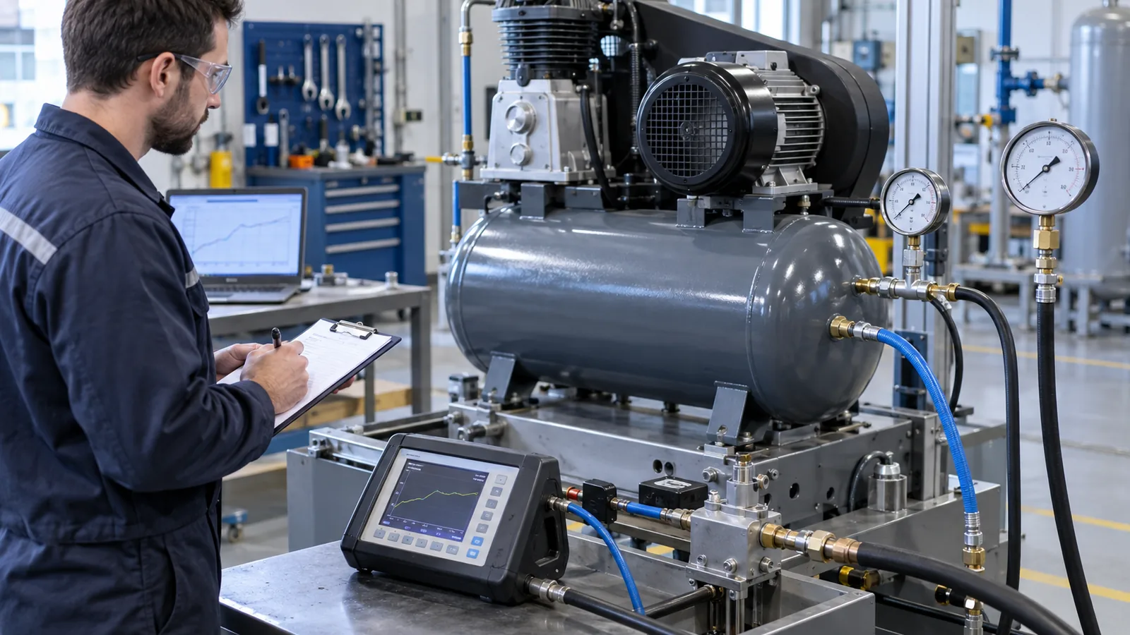
Distribution piping should be sized for the required flow, not merely for the compressor outlet thread. Long undersized lines, restrictive quick couplers, clogged filters and excessive hose length all consume pressure. Install isolation, drainage and treatment equipment so maintenance can be performed without contaminating the downstream process. Use a commissioning sheet that records unloaded and loaded pressure, running current, temperature, drain operation and any abnormal noise or vibration.
Maintenance and inspection priorities
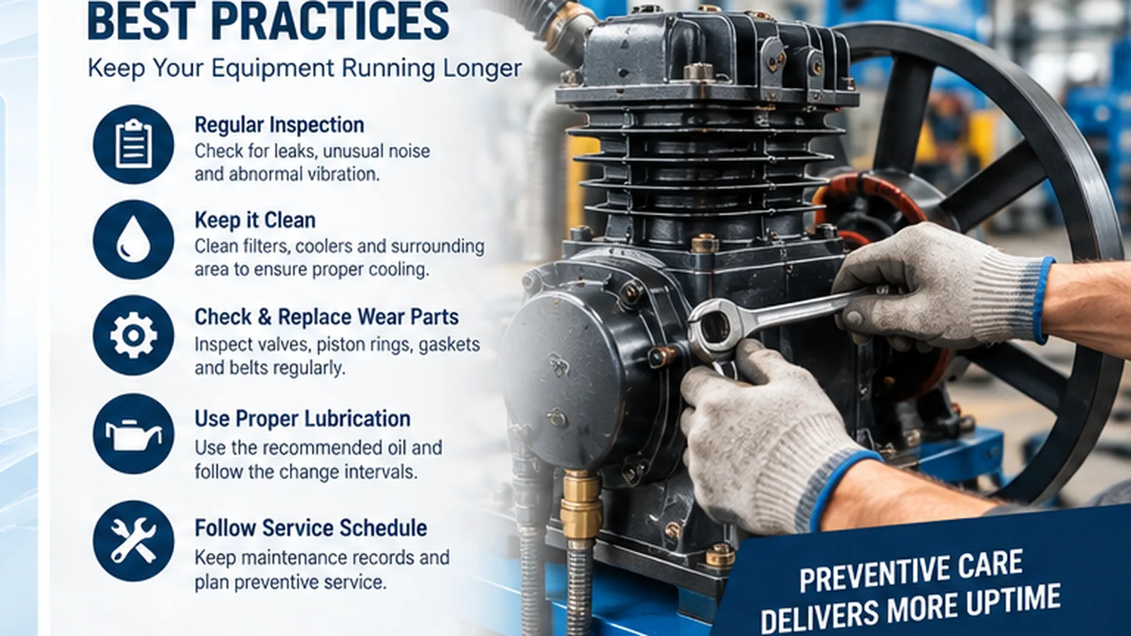
Routine maintenance begins with clean intake air, correct lubrication where the compressor design uses lubricant, condensate management, secure connections and unobstructed cooling. A rising discharge temperature, longer recovery time, repeated pressure-switch cycling or unusual vibration should be investigated rather than treated as normal aging. Filter condition and air leaks are frequent, inexpensive checks before major components are suspected.
For receiver systems, drain condensate at a frequency suited to humidity and usage, inspect the tank and fittings, and verify that gauges and controls respond consistently. For screw packages, use the specified maintenance plan for air, water and oil circuits as applicable to the selected series. Record service dates and running conditions so a change in performance can be compared with a known baseline. The site’s maintenance guide provides a broader checklist; you can use the air-compressor selection guide for the application context.
Quality verification and RFQ preparation
Before release, verification should focus on the parameters that determine fit: model identity, electrical supply, pressure setting, air-delivery requirement, receiver or package arrangement, outlet connection and external dimensions. Where an incoming inspection plan is required, add checks for visible shipping damage, fastener condition, electrical panel integrity, leakage and functional response. Dimensional or interface-critical projects should include a drawing rather than relying on a photograph.
For a useful quotation, send the model or performance target, quantity, destination country, voltage/frequency, target pressure, required flow, duty pattern and any air-quality requirement. If the compressor will be integrated into a machine, include the installation envelope and connection points. You can review application planning to organize those inputs before sending the RFQ.
Frequently asked questions
Should I choose from motor power or air delivery?
Use required pressure and usable air delivery first. Motor power is an important constraint, but it does not by itself tell you whether a tool or process will receive enough air at its working pressure.
Can a larger receiver make an undersized compressor adequate?
A larger receiver can buffer short peaks and reduce cycling, but continuous demand eventually depends on compressor delivery. Sustained users must be matched to the required flow.
What should I provide for an export quotation?
Provide destination, voltage and frequency, pressure, flow, duty hours, installation environment, quantity, connection requirements and any air-quality or documentation needs.
Are the application images guaranteed installations?
No. They show typical use contexts. Final selection should be based on the actual pneumatic load, environment and integration details.
Procurement decision notes
A compressor purchase should be evaluated as a system decision. A compressor purchase should be evaluated as a system decision. A compressor purchase should be evaluated as a system decision. A compressor purchase should be evaluated as a system decision. A compressor purchase should be evaluated as a system decision. A compressor purchase should be evaluated as a system decision. A compressor purchase should be evaluated as a system decision. A compressor purchase should be evaluated as a system decision. A compressor purchase should be evaluated as a system decision. A compressor purchase should be evaluated as a system decision. A compressor purchase should be evaluated as a system decision. A compressor purchase should be evaluated as a system decision. A compressor purchase should be evaluated as a system decision. A compressor purchase should be evaluated as a system decision. A compressor purchase should be evaluated as a system decision. A compressor purchase should be evaluated as a system decision. A compressor purchase should be evaluated as a system decision. A compressor purchase should be evaluated as a system decision. A compressor purchase should be evaluated as a system decision. A compressor purchase should be evaluated as a system decision. A compressor purchase should be evaluated as a system decision. A compressor purchase should be evaluated as a system decision. A compressor purchase should be evaluated as a system decision. A compressor purchase should be evaluated as a system decision. A compressor purchase should be evaluated as a system decision.