
Wählen Sie anhand der tatsächlichen Flugnachfrage, nicht nur anhand des Kategorienamens.
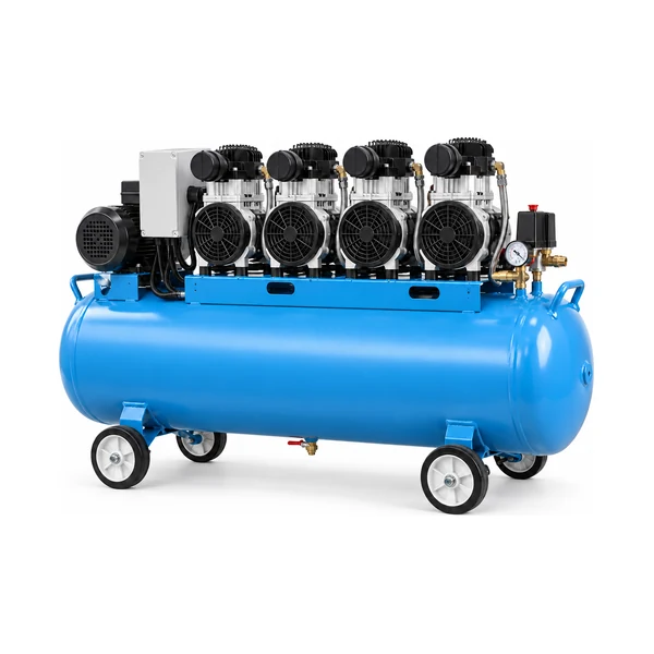
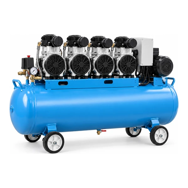
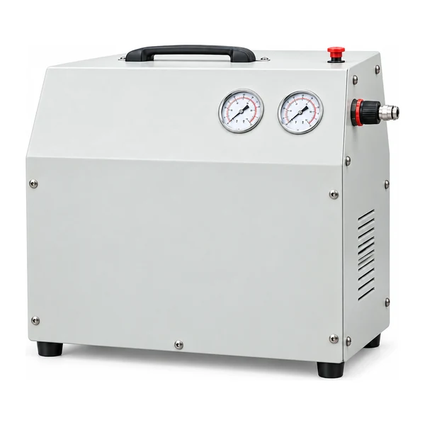
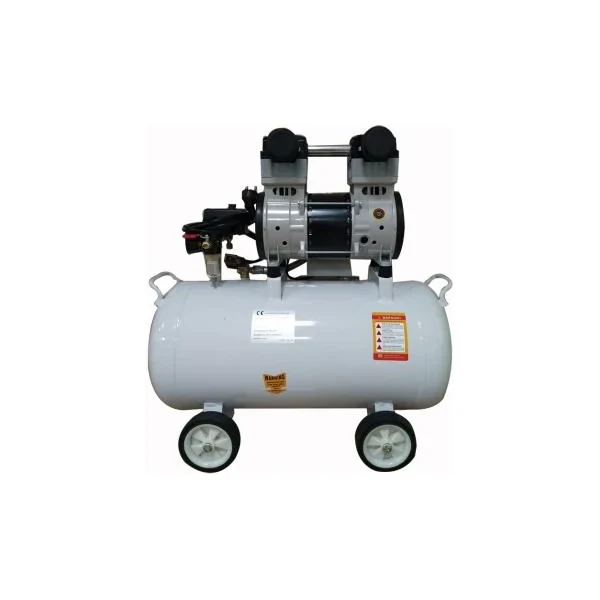
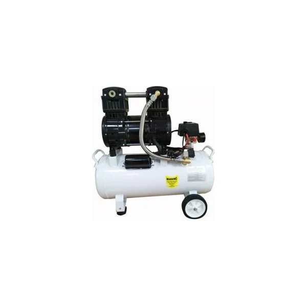
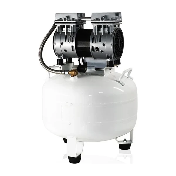
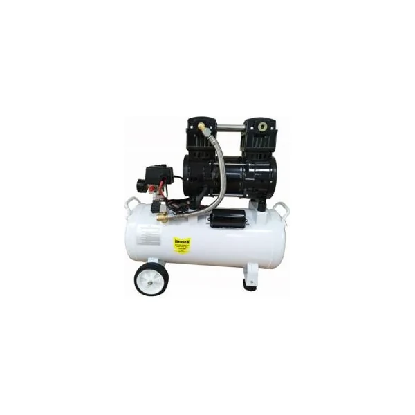
Die Kategorie „Geräuscharme, ölfreie Druckluftkompressoren“ umfasst verschiedene Behältergrößen – von kompakten Geräten bis hin zu größeren Mehrmotorenkonfigurationen – mit dokumentierten Daten zu Elektrik, Luftdurchsatz, Abmessungen und Gewicht. Diese Kategorie richtet sich an Käufer, die bereits wissen, dass die Kompressorfamilie relevant ist, aber noch entscheiden müssen, welcher Druck, welcher Durchfluss und welche Bauform für ihr Projekt am besten geeignet sind. Beginnen Sie mit der pneumatischen Last, ermitteln Sie, ob der Bedarf kontinuierlich oder intermittierend ist, und vergleichen Sie anschließend die unten aufgeführten, geprüften Produkte.
Typische Einsatzgebiete sind Werkstätten, Werkbänke, der Einsatz mit intermittierendem Druckluftbetrieb und die Unterstützung von Anlagen, wo ölfreie Kompression und eine praktische Behälteraufbewahrung von Vorteil sind. Ist der Betriebspunkt unklar, sollte man sich zunächst am konkreten Werkzeug oder Prozess orientieren, anstatt das größte Modell zu wählen. Eine Überdimensionierung kann unnötige Investitions- und Betriebskosten verursachen, während eine Unterdimensionierung zu niedrigem Betriebsdruck, langsamer Druckwiederherstellung oder übermäßiger Laufzeit führen kann.
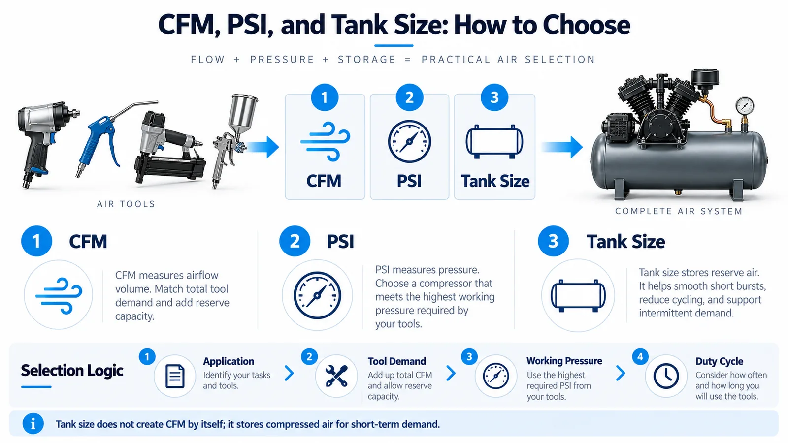
Auswahlvariablen, die das Ergebnis ändern
Erfassen Sie den Zieldruck beim Anwender, den gleichzeitigen Luftbedarf, die Betriebsstunden, den zulässigen Druckabfall, die Umgebungstemperatur, die Stromversorgung, die Kühlmethode, den Platzbedarf und die Anforderungen an die Wartungszugänglichkeit. Bei Druckluftspeichersystemen beeinflusst das Tankvolumen das Verhalten des Kompressors bei kurzzeitigen Druckspitzen. Bei Schraubenkompressoren sind Kühlung und Belüftung Bestandteil der Auslegung. Bei Geräten mit einem Betriebsdruck von 20–40 bar muss die Druckfestigkeit für jede angeschlossene Komponente, nicht nur für den Kompressor, überprüft werden.
Nutzen Sie die Produktübersicht als Vorauswahlliste und dann Vergleichen Sie die zugehörige KompressorfamilieKäufer, die die Installationsbedingungen vergleichen möchten, können Nutzen Sie den Auswahlleitfaden für Luftkompressoren.prozessspezifische Benutzer sollten auch Überprüfung der Antragsplanung vor der Herausgabe der Kaufspezifikation.
Installations- und Wartungshinweise
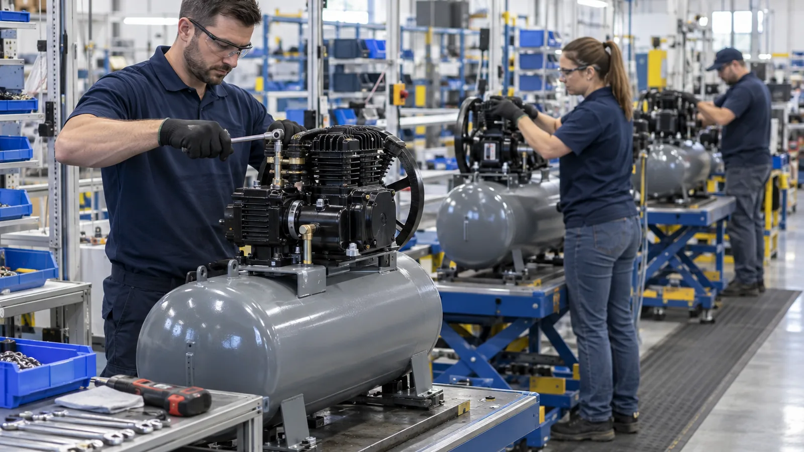
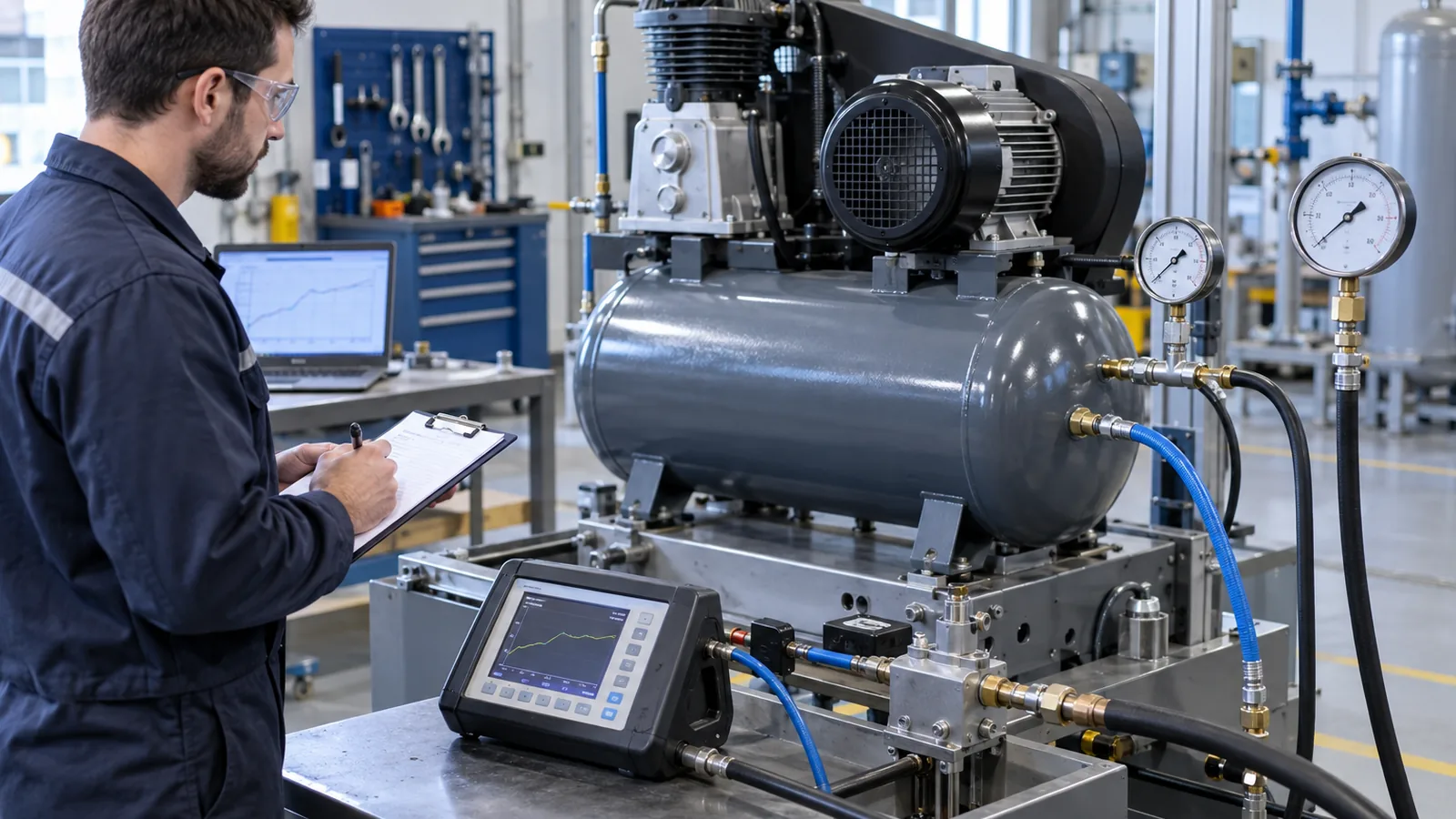
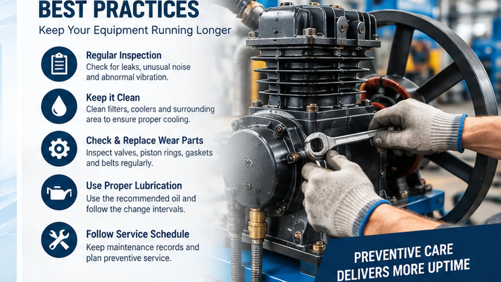
Eine fachgerechte Installation gewährleistet die auf dem Papier ermittelten Leistungswerte. Sorgen Sie für saubere Ansaugluft, ausreichende Wärmeabfuhr, dimensionieren Sie die Verteilerleitung entsprechend dem tatsächlichen Durchfluss und gewährleisten Sie eine Kondensatableitung. Lassen Sie ausreichend Freiraum um Filter, Paneele, Ventile und Kühlflächen. Ermitteln Sie bei der Inbetriebnahme einen Referenzwert für Druck, Stromstärke, Temperatur und Wärmerückgewinnung, um spätere Wartungsarbeiten mit diesen Betriebsdaten vergleichen zu können.
Checkliste für Angebotsanfragen
Bitte geben Sie, falls bekannt, das bevorzugte Modell an oder liefern Sie Angaben zu Druck, Durchfluss, Spannung/Frequenz, Betriebsart, Menge, Bestimmungsort und Einbauort. Ergänzen Sie dies um die Anforderungen an Anschluss und Luftqualität, wenn der Kompressor Teil einer größeren Anlage ist. Spezielle Prozessanforderungen sollten vor der Angebotserstellung und nicht erst nach der Bestellung der Ausrüstung definiert werden.
Häufig gestellte Fragen
Können die Modelle dieser Kategorie nur nach PS oder kW ausgewählt werden?
Nein. Die Motorleistung ist nur ein Faktor. Vergleichen Sie die nutzbare Fördermenge bei dem erforderlichen Druck und prüfen Sie anschließend Betriebs-, Speicher-, Kühl-, Stromversorgungs- und Verteilungsverluste.
Was passiert, wenn meine Nachfrage während der Schicht stark schwankt?
Geben Sie ein Lastprofil mit Spitzendurchfluss, Durchschnittsdurchfluss und Spitzendauer an. Die Dimensionierung anhand eines einzelnen Durchschnittswerts kann sinnvoller sein als die Verwendung eines Druckspeichers, eines variablen Betriebs oder mehrerer Kompressoren.
Wie vergleiche ich am besten zwei ähnliche Modelle?
Vergleichen Sie den erforderlichen Betriebspunkt mit dem dokumentierten Bereich jedes Modells und bewerten Sie anschließend Platzbedarf, Kühlung, Anschlussgrößen, Servicezugang und zukünftiges Lastwachstum.
Betriebsbedingungen, die in der Spezifikation angegeben werden sollten
Eine aussagekräftige Spezifikation für geräuscharme, ölfreie Tankluftkompressoren unterscheidet den normalen Betriebspunkt vom anspruchsvollsten realen Betrieb. Erfassen Sie Umgebungstemperatur, Ansaugluftreinheit, Luftfeuchtigkeit, gegebenenfalls Höhenlage, Betriebsstunden, Anläufe oder Laständerungen sowie den minimal zulässigen Druck am Anwender. Notieren Sie bei bestehenden Systemen, ob der Bedarf konstant oder saisonal ist und ob Druckprobleme während einer bestimmten Schicht oder eines bestimmten Prozessschritts auftreten. Diese Beobachtungen erklären oft, warum zwei Anlagen mit der gleichen Nennleistung des Kompressors unterschiedliche Leistungen erbringen können.
Die Details der Verteilung gehören in dieselbe Spezifikation. Rohrdurchmesser, Schlauchlänge, Filter, Trockner, Ventile und Schnellkupplungen erzeugen Widerstand. Ein Kompressor sollte nicht automatisch vergrößert werden, um ein restriktives Verteilungsnetz auszugleichen. Messen Sie den Druck in der Nähe des Kompressors und erneut beim Verbraucher während der Spitzenlast; eine große Differenz deutet eher auf Systemverluste als auf unzureichende Kompressionsleistung hin. Diese Unterscheidung verhindert unnötige Geräteerweiterungen und erleichtert die Überprüfung von Korrekturmaßnahmen.
Betriebsfähigkeit, Inbetriebnahme und langfristige Betriebsdisziplin
Die Wartungszufahrt sollte vor der Anlieferung der Maschine geplant werden. Filter, Abflüsse, Bedienfelder, Kühler und Anschlüsse müssen erreichbar sein. Der Kompressor darf nicht so platziert werden, dass heiße Abluft in den Ansaugkanal zurückgesaugt wird. Bei der Inbetriebnahme sollte ein Referenzwert ermittelt werden, der Lastdruck, Betriebsstrom, Temperatur, Erholungs- bzw. Lastverhalten, Funktion des Abflusses und ungewöhnliche Geräusche umfasst. Dieser Referenzwert ist aussagekräftiger als ein allgemeines Wartungsintervall, da er den Technikern einen bekannten, einwandfreien Zustand als Vergleichsgrundlage bietet.
Untersuchen Sie während des Betriebs eher Trends als einzelne Symptome. Steigende Temperaturen, längere Erholungszeiten, häufiges Ein- und Ausschalten oder ein allmählicher Druckabfall am Einsatzort können auf verstopfte Filter, Leckagen, nachlassende Kühlung oder veränderte Anlagenanforderungen hinweisen. Dokumentieren Sie die Veränderungen und überprüfen Sie deren Wirkung nach der Wartung. Bei Hochdruckanlagen erfordern die Absperrvorrichtungen und die druckbelasteten nachgeschalteten Komponenten besondere Aufmerksamkeit; bei Reinluft bleiben die nachgeschaltete Aufbereitung und die Kondensatkontrolle auch dann wichtig, wenn die Verdichtungsstufe ölfrei ist.
Konfigurationsübergabe vor Angebotserstellung
Bevor ein Modell in der Geräuscharme, ölfreie Tankluftkompressoren Sobald die Produktfamilie zur Angebotserstellung freigegeben ist, fassen Sie bitte die Betriebspunkte und Installationsannahmen in einem Übergabeprotokoll zusammen. Geben Sie den Druck am Einsatzort, den erwarteten gleichzeitigen Luftdurchsatz, die tägliche Betriebsdauer, die längste Dauerlaufzeit, die Stromversorgung, die Umgebungsbedingungen, die Rohrleitungslänge, die Anforderungen an die Luftqualität und den verfügbaren Installationsraum an. Bei Behältersystemen geben Sie bitte die erwartete Spitzendruckdauer und die erforderliche Wiederherstellungszeit des Behälters an. Bei Schraubenkompressoren und Hochdruckanlagen sind die Kühlbedingungen, der Auslassanschluss und die Druckfestigkeit aller nachgeschalteten Komponenten, die dem gewählten Druck ausgesetzt sind, anzugeben.
Ziel der Übergabe ist die nachvollziehbare Modellvergleichbarkeit. Ist ein Wert noch unbekannt, ermitteln Sie das Werkzeug, den Prozess oder die vorhandene Maschine, die den Bedarf erzeugt, anstatt willkürlich eine Reserve einzufügen. Bei ähnlichen Modellen vergleichen Sie die gelieferte Luftmenge bei erforderlichem Druck, die Wartungszugänglichkeit, den Platzbedarf und die Sicherheitsmarge über dem realistischen Spitzenwert. Die endgültige Auswahl sollte die Konfiguration sein, die den tatsächlichen Betriebspunkt mit einer vertretbaren Sicherheitsmarge erfüllt und sich korrekt installieren, kühlen, entleeren und warten lässt.