
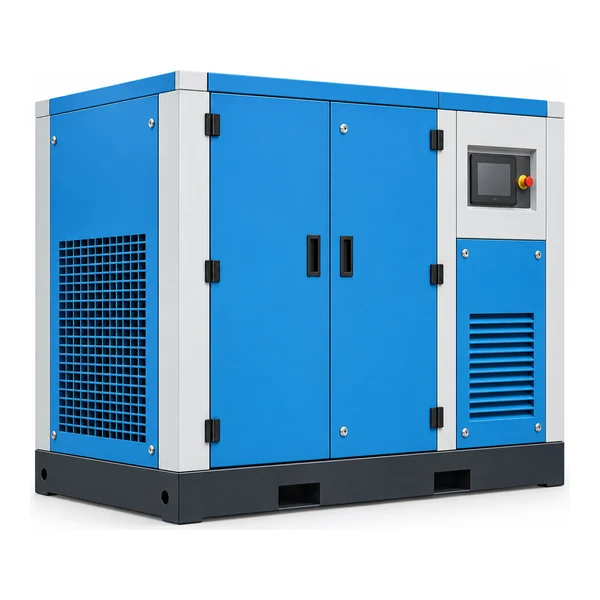
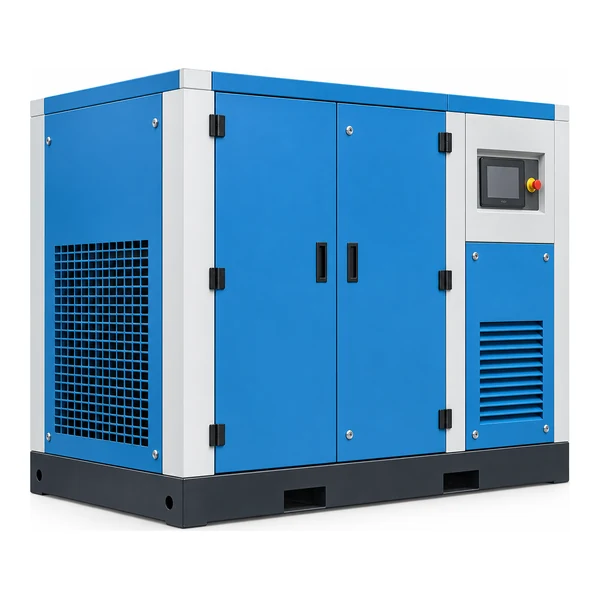
Elija según la demanda real de aire, no solo según el nombre de la categoría.
La categoría Compresores de aire de media y alta presión abarca configuraciones de tornillo sin aceite y con microaceite de 20 a 40 bar, con datos documentados de caudal, potencia del motor, salida y dimensiones. Está organizada para compradores que ya conocen la familia de compresores, pero aún necesitan decidir qué presión, caudal y configuración física se ajustan mejor a su proyecto. Comience con la carga neumática, identifique si la demanda es continua o intermitente y, a continuación, compare las filas de productos verificadas que se muestran a continuación.
El ajuste típico incluye procesos que requieren una presión superior a la del aire comprimido estándar del taller y una verificación precisa de la clase de presión aguas abajo. Si el punto de operación es incierto, comience con la herramienta o el proceso real en lugar de seleccionar el modelo más grande. Un sobredimensionamiento puede generar costos de capital y operación innecesarios, mientras que un sobredimensionamiento puede provocar baja presión en el punto de uso, una recuperación lenta o un tiempo de funcionamiento excesivo.
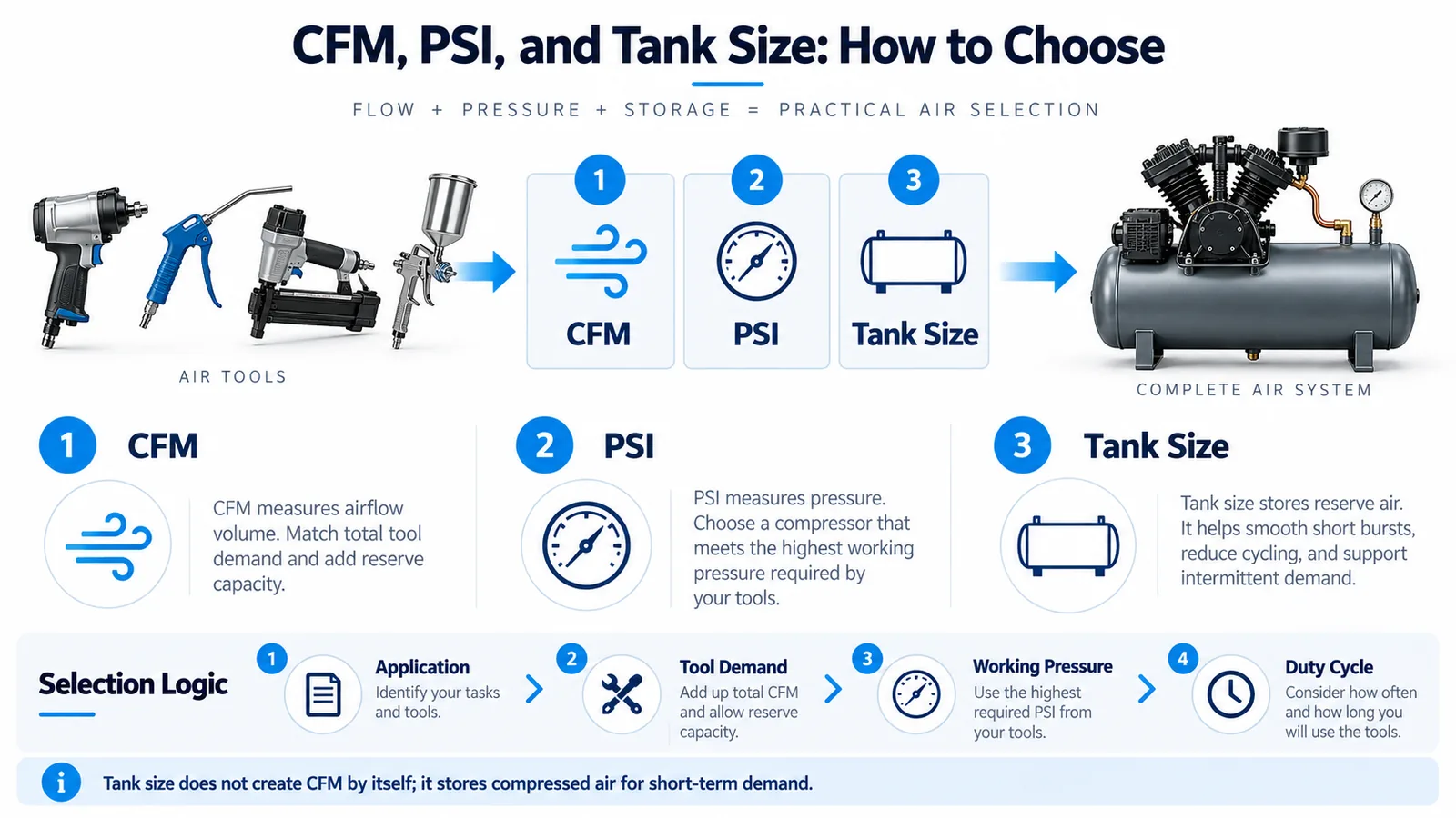
Variables de selección que modifican el resultado
Registre la presión objetivo en el usuario, la demanda de aire simultánea, las horas de funcionamiento, la caída de presión admisible, la temperatura ambiente, el suministro eléctrico, el método de refrigeración, el espacio ocupado y las necesidades de acceso para el mantenimiento. En los sistemas de depósito, el volumen del tanque afecta la forma en que el compresor gestiona los picos de presión puntuales. En los sistemas de tornillo, la refrigeración y la ventilación forman parte del diseño. Para equipos de 20 a 40 bar, se debe confirmar la presión nominal de cada componente conectado, no solo del compresor.
Utilice la cuadrícula de productos como una lista corta y luego comparar la familia de compresores relacionadaLos compradores que deseen comparar las condiciones de instalación pueden Utilice la guía de selección de compresores de aire.; los usuarios específicos del proceso también deberían revisar la planificación de la aplicación antes de emitir las especificaciones de compra.
Consideraciones sobre la instalación y el mantenimiento
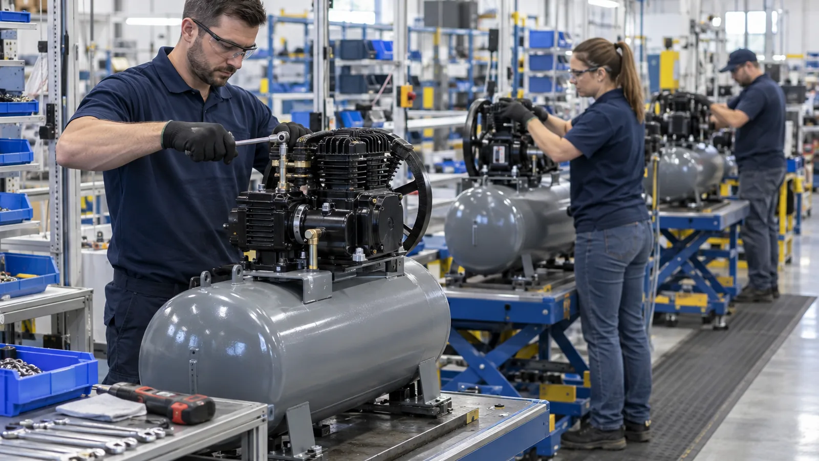
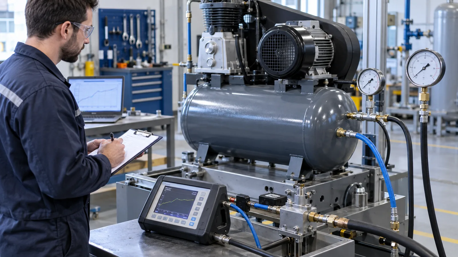
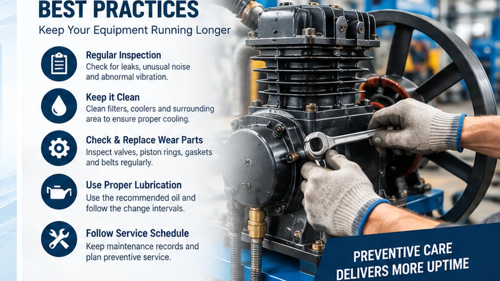
Una buena instalación preserva el rendimiento previsto inicialmente. Mantenga limpio el aire de admisión, asegure una adecuada disipación de calor, dimensione la línea de distribución según el caudal real y proporcione drenaje donde se acumule el condensado. Deje espacio libre alrededor de filtros, paneles, válvulas y superficies de refrigeración. Establezca una línea base de puesta en marcha para la presión, la corriente, la temperatura y el comportamiento de recuperación, de modo que el mantenimiento posterior pueda compararse con los datos operativos conocidos.
Lista de verificación de RFQ
Indique el modelo preferido si lo conoce, o proporcione la presión, el caudal, la tensión/frecuencia, el ciclo de trabajo, la cantidad, el destino y el espacio de instalación. Incluya los requisitos de conexión y calidad del aire si el compresor forma parte de una máquina más grande. Los requisitos especiales del proceso deben definirse antes de la cotización, no después de realizar el pedido.
Preguntas frecuentes
¿Se pueden seleccionar los modelos de esta categoría únicamente por potencia (HP) o kilovatios (kW)?
No. La potencia del motor es solo una variable. Compare el caudal útil a la presión requerida y luego verifique el funcionamiento, el almacenamiento, la refrigeración, el suministro eléctrico y las pérdidas de distribución.
¿Qué ocurre si mi demanda varía drásticamente durante el turno?
Proporcione un perfil de carga con caudal máximo, caudal promedio y duración máxima. El almacenamiento en depósito, el funcionamiento variable o el uso de múltiples compresores pueden ser más apropiados que dimensionar a partir de un único valor promedio.
¿Cómo debo comparar dos modelos similares?
Compare el punto de funcionamiento requerido con el rango documentado de cada modelo y, a continuación, evalúe el espacio que ocupa, la refrigeración, el tamaño de las conexiones, el acceso al servicio y el crecimiento futuro de la carga.
Condiciones de funcionamiento que deben indicarse en la especificación.
Una especificación útil para compresores de aire de media y alta presión distingue el punto de operación normal de la condición realista más exigente. Registre la temperatura ambiente, la limpieza del aire de admisión, la humedad, la altitud (cuando corresponda), las horas de funcionamiento, los arranques o cambios de carga y la presión mínima aceptable para el usuario. Para un sistema existente, observe si la demanda es estable o estacional y si se producen problemas de presión durante un turno o etapa de proceso específicos. Estas observaciones suelen explicar por qué dos instalaciones que utilizan el mismo tamaño nominal de compresor pueden tener un rendimiento diferente.
Los detalles de la distribución deben incluirse en la misma especificación. El diámetro de las tuberías, la longitud de las mangueras, los filtros, los secadores, las válvulas y los acoplamientos rápidos generan resistencia. No se debe sobredimensionar automáticamente un compresor para compensar una red de distribución restrictiva. Mida la presión cerca del compresor y nuevamente en el punto de consumo durante la demanda máxima; una gran diferencia indica una pérdida del sistema, en lugar de una capacidad de compresión insuficiente. Esta distinción evita la ampliación innecesaria del equipo y facilita la verificación de las medidas correctivas.
Disciplina de mantenimiento, puesta en marcha y operación a largo plazo
El acceso para el mantenimiento debe diseñarse antes de la llegada de la máquina. Mantenga accesibles los filtros, desagües, paneles de control, enfriadores y puntos de conexión, y evite ubicar el compresor en un lugar donde el aire caliente de escape sea aspirado hacia la entrada. La puesta en marcha debe establecer una línea base que incluya la presión bajo carga, la corriente de funcionamiento, la temperatura, el comportamiento de recuperación o carga, el funcionamiento del desagüe y las observaciones de ruidos anormales. Esta línea base es más útil que un intervalo de mantenimiento genérico, ya que proporciona a los técnicos un estado de funcionamiento óptimo conocido para su comparación.
Durante el servicio, investigue las tendencias en lugar de los síntomas aislados. El aumento de la temperatura, una recuperación más prolongada, los ciclos frecuentes o una pérdida gradual de la presión en el punto de uso pueden indicar obstrucción del filtro, fugas, deterioro del sistema de refrigeración o cambios en la demanda de la planta. Registre los cambios y confirme el efecto después del mantenimiento. Para equipos de alta presión, el aislamiento y los componentes posteriores con capacidad de presión requieren especial atención; para aire de proceso limpio, el tratamiento posterior y el control del condensado siguen siendo importantes incluso cuando la etapa de compresión no utiliza aceite.
Transferencia de configuración antes de la cotización
Antes de un modelo en el Compresores de aire de media y alta presión Se libera la familia para cotización, mantenga el punto de operación y los supuestos de instalación en un registro de entrega. Indique la presión en el punto de uso, el flujo de aire simultáneo esperado, el servicio diario, el funcionamiento continuo más largo, el suministro eléctrico, las condiciones ambientales, la distancia de la tubería, los requisitos de calidad del aire y el espacio de instalación disponible. Para sistemas receptores, incluya la duración del pico esperada y la rapidez con la que el receptor debe recuperarse. Para paquetes de tornillo y de alta presión, incluya las condiciones de refrigeración, la conexión de salida y la presión nominal de cada componente aguas abajo que estará expuesto a la presión seleccionada.
El objetivo de la transferencia es que la comparación de modelos sea auditable. Si aún se desconoce un valor, identifique la herramienta, el proceso o la máquina existente que genera la demanda, en lugar de insertar una reserva arbitraria. Cuando dos modelos son similares, compare el aire suministrado a la presión requerida, el acceso para el servicio, el espacio ocupado y el margen por encima del pico realista. La selección final debe ser la configuración que cumpla con el punto de operación real con un margen justificable y que pueda instalarse, refrigerarse, drenarse y mantenerse correctamente.